
All buyer guides · · OPINOX
Fit the first molded outlet cover to the intended inner baffle and housing. Check how the outlet locates and seats, then operate the unit at the agreed water levels and settings. Observe mist routing and where condensation collects. Remove, clean and refit the cover once more before approving the assembly.
In this guide
- Use the inner mist path to locate the outlet
- Map the condensation and repeat the check after cleaning
- Build a repeatable first-sample check
- Choose the reference assembly before the first molded parts arrive
- Inspect individual dimensions and the assembled stack
- Write an operating observation sheet that two teams can reproduce
- Compare new and serviced assemblies
- Keep the issue record actionable for tooling and product teams
- RFQ questions and answers
Use the inner mist path to locate the outlet
Review a section through the tank, inner baffle and outlet cover. Identify the surfaces or locating features that set the outlet position, engagement direction and seated height. Use those same references on the inspection drawing so everyone checks the same assembled position.
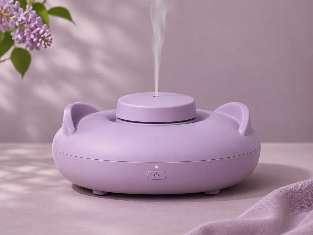
For example, an outlet may look centered on the housing while its internal opening partially overlaps the baffle. On a first shot, photograph the seated assembly from the side, then look through the assembled opening or inspect a sectioned fit sample. A MUJI diffuser manual documents one real assembly in which cover alignment and seating affect mist operation. Its geometry and operating values are specific to that model.
Map the condensation and repeat the check after cleaning
Use the intended tank, ultrasonic module and fan where applicable. Define the fill levels, operating settings, run duration and room conditions for the acceptance check. Observe whether droplets stay on a specified wet surface, return toward the tank or reach areas that should remain dry. Visible plume appearance can also change with room conditions, so agree how to record observations and avoid using one photo as the sole acceptance criterion.
After the run, follow the product team’s safe servicing procedure and check whether the user can access the intended cleaning areas. Remove and refit the cover several times under the agreed test. Mark any incomplete seating that looks closed, awkward cleaning access, loosened locating features or new drips after reassembly.
Build a repeatable first-sample check
Per sample, identify the molded cover, mating part revisions and operating conditions. Inspect fit with the same reference points even if two covers can be assembled by hand. Agree with the product team who evaluates mist operation and who adjusts the molded part when seating or alignment is outside the agreed range.
- Section drawing with inner and outer outlet geometry and locating surfaces.
- Photos of the correctly seated assembly and any partial-seating condition.
- Agreed run settings, water levels, observation period and wet/dry boundaries.
- Repeat fit and operation checks after the specified cleaning and refitting procedure.
Choose the reference assembly before the first molded parts arrive
Create a reference pack with the inner path drawing, housing revision, tank and outlet part identities, and photos of a correctly seated sample if one already exists. Record the planned orientation for the product and the direction in which the outlet cover is inserted or rotated. This gives the tooling supplier a stable reference even when the electronic system, fan or cosmetic exterior comes from a different team.
Agree on a reference for position, depth and rotation. A designed stop may control depth, while a slot or locating tab controls rotation. Identify how to check that the part has actually reached the stop. For example, an inspection mark might line up only when the cover is fully seated. Keep dimensions that control the mist path separate from decorative offsets, and show which surfaces establish the assembly reference.
Inspect individual dimensions and the assembled stack
Check critical locating features on the unassembled cover, then fit it to the actual cover receiver and baffle. Record whether it can be placed incorrectly while still looking closed. A cover that rocks, catches on a nearby lip or returns to different positions each time needs follow-up even if each component is within a separate drawing measurement.
A hypothetical two-piece cover uses an outer shell with a decorative slot and an inner insert that guides mist toward it. Test the drawing with the two parts assembled at the same reference point. Inspect the overlap of the two openings rather than measuring only the slot width. A removable fit template or a sectioned development sample may make the difference easier to see. Mark the contact points found on the real assembly and update the inspection sketch if the original datum is hard to reach.
Write an operating observation sheet that two teams can reproduce
Use the intended module and the same assembly conditions as the agreed product test. Note which water level, mode, test duration, room conditions and orientation apply to each run. Ask the product team which safe operating limits must be followed and which situations are part of approval. Keep a log of what you can observe, including startup, whether the direction of the plume is consistent with the target, when droplets begin to form and where moisture collects.
If two assembly revisions will be compared, change only the candidate cover and record what remains fixed. That helps teams tell whether a difference occurred with the revised fit or merely on a different day with a different setup. Carry the intended dry-zone map into the log so users can tell whether a drop has crossed into a restricted area. When repeats are needed, specify whether the unit is dried between runs and whether removed parts are refitted by the same procedure.
Compare new and serviced assemblies
Review how a person reaches the surfaces that need cleaning. An accessible outlet is useful only when the product’s intended procedure can restore the cover to the right location. Use the planned service tools and access method. Check whether an operator can mistakenly turn the cover to an apparently usable position, whether inserts stay captive where intended and whether normal reinsertion damages the locating details.
For a conceptual bayonet cover, for example, verify that a short turn engages the intended stop and that a witness mark or tactile cue corresponds to actual seating. Repeat the same mist and condensation observations after the agreed cleaning and refit. Record any changes in assembly feel separately from evidence about liquid routing and plume direction. A fit change is an observation that may justify another controlled check even if the first visible mist result still looks acceptable.
Include the assembly cycle in the handover. If a trial used a new tank for every cover, note that fact and decide whether the routine inspection should also check fit to an already serviced tank. Carry forward any approved limits on wear of the locating tabs and the method for noticing fit loss.
Keep the issue record actionable for tooling and product teams
Identify each failed check, the exact parts paired in that run and the condition under which it failed. A short video may show what happens after refitting, while a labeled section photo better explains a blocked opening or a contact point. Connect each record to the drawing revision and sample ID. Describe what the inspector observed before suggesting which part to change.
After a trial adjustment, repeat the failed check and the nearby checks that could be affected. Moving a stop might improve opening overlap while changing removal clearance or the fit to a trim piece. The recheck should cover those connected functions. Agree on who signs dimensional fit, who signs operating performance, and where both sign-offs are recorded. This allocation helps avoid treating a single molded cover’s dimensions as evidence of full system performance.
Buyer questions
Can I approve the mist outlet cover by itself?
You can inspect its individual dimensions. To sign off mist-path alignment, seating and cleaning access, check the cover with the actual mating parts.
Where should an inspection record condensation?
Note the exact surface and when liquid first appeared. Distinguish the intended wet path from adjacent areas that must stay dry, according to the assembly requirements.
RFQ questions and answers
What drawings should I send for a diffuser mist outlet cover quote?
Send the cover CAD, a section of the intended mist path, the baffle and housing revisions, and the locations that control seating and rotation. Identify the planned finish, whether the cover is removable for cleaning, and the required trial and order quantities.
Can I request a sample quote before I have the final electronics?
Ask for a separate sample scope that checks molded dimensions and dry assembly with the available housing and baffle. List the module, fan or other hardware still pending. Plan the operating checks after those parts are defined and the intended system can be assembled.
Who should provide the mating components and test fixture?
Name who will supply the tank, baffle, housing, module and any adjustable fixture. State the revisions or make clear which ones remain open. Ask the quote to show if samples are returned after inspection and which replacement parts will be available for repeat tests.
Should I ask suppliers to quote both a snap cover and a bayonet cover?
Compare the two concepts only against the same mist-path section, service access and acceptance requirements. Request separate tooling, sample and inspection line items. Ask what extra geometry, assembly operations or tooling changes each alternative would require without assuming the mechanisms are interchangeable.
How should I specify a retest after an outlet design revision?
Share the previous result and mark what changed in the drawing. Request verification of the previously failed check and related functions, such as seating, opening overlap, cleaning access and moisture routing. Define how many samples and which assembled configurations are appropriate for the affected changes.
Related products and services
Discuss this project with OPINOX →